ZT-RY-909 is a high-performance UHF smart splitter, completely design by independent intellectual property, combined with a proprietary intelligent recognition algorithms, can achieve up to 32 sub-splitter and 256 antenna of any access, and to provide real-time current antenna connection, thus completing all the way of the UHF reader radio switching to any of the 256 antennas and output. Can be used for networking and real-time item-level asset tracking, smart shelves allocated among the shelves and its application of RFID antennas and electronic tags.
FEATURES
> Self-intellectual property ;
> Frequency range support 860 ~ 960MHz;
> Simple physical connection, sub-splitter without take the circuit lines additional, complex RF transmission with coaxial cable, with the main splitter to take power, communications;
> The power-on query automatic for the access state of the sub-splitter and the antenna, and supports the dynamic update the current connection;
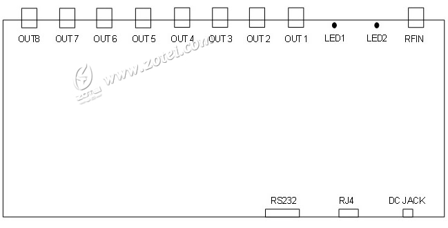
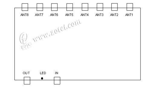
> 8 MCX output interface, each interface supports four sub-splitter cascade, can also be used as the antenna interface to access the antenna. Each sub-splitter can access up to 8 antenna, so a primary splitter output interface can connect up to 32 antennas;
> Supports up to 256 antenna switch, and antenna switching speed of less than 100ms;
> RF input RF transmission line to the antenna end of the distance up to 10m or more;
> Low-power design, single +9 V power supply;
> Support for user interface such as RS232 and TCPIP network;
> High reliability design for harsh environment;
> Size: H200mm × W105mm × T28mm (Master), Weight 1.2kg;
> Size: H125mm × W59mm × T17mm (Slave), Weight: 230g.
MASTER INTERFACE
The main tap interface:

1. Power Supply DC JACK
| No. |
Symbol |
Comment |
| Central |
PWR |
+9V power supply |
| Outer |
GND |
Ground |
2. Serial Port RS232 (DB9 Female)
| No. |
Symbol |
Comment |
| 1 |
Output1 |
Reserved |
| 2 |
Output2 |
RS232 serial data output |
| 3 |
Output3 |
RS232 serial data input |
| 4 |
Output4 |
Reserved |
| 5 |
Output5 |
Ground |
| 6 |
Output6 |
Reserved |
| 7 |
Output7 |
Reserved |
| 8 |
Output8 |
Reserved |
| 9 |
TGIN |
Reserved |
3. TCP/IP (10M/100M) Socket RJ45
4. MCX(Female)RF Output OUT1~OUT8
5. SMA (Female) RF Input RFIN
6. Indicator
| No. |
Symbol |
Comment |
| 1 |
LED1 |
Working indicator |
| 2 |
LED2 |
Power on indicator |
Sub-tap interface:

Slave Interface
1. MCX RF Input IN
2. MCX RF Cascade Output OUT
3. MCX Antenna Port ANT1~ANT8
4. Working Indicator LED
CHARACTERISTICS
> Absolute Maximum Rating
| ITEM |
SYMBOL |
VALUE |
UNIT |
| Power Supply |
VCC |
45 |
V |
| Operating Temp |
TOPR |
-10~+55 |
℃ |
| Storage Temp |
TSTR |
-20~+75 |
℃ |
> Electrical and Mechanical Specification
Under TA=25℃,VCC=+9V unless specified
| ITEM |
SYMBOL |
MIN |
TYP |
MAX |
UNIT |
| Power Supply |
VCC |
7 |
9 |
40 |
V |
| Current Dissipation |
IC |
170 |
200 |
300 |
mA |
| Frequency |
FREQ |
860 |
|
960 |
MHz |
| RF Output Power |
Pout |
|
|
36 |
dBm |
* Effective distance depends on protocol, tag and environment.
Download
Software Development Kit
|


